I recently received the pair of TCP subframe connectors that I ordered and wanted to test fit them to get an idea of how they were going to work out.
There are a bunch of subframe connector options out there. I settled on TCP because I wasn’t a fan of tubular designs and wanted ones that tucked up as tightly to the floor as possible. From the TCP installation manual it sounded like their subframe connectors are expected to make direct contact with the underside of the floor, potentially requiring some force from below during install to seat properly. Since I plan to install the subframe connectors before the floor that means I’ll likely be dealing with the interference from the opposite direction – needing to apply downward pressure on the floor around the contact points with the subframe connectors during installation.
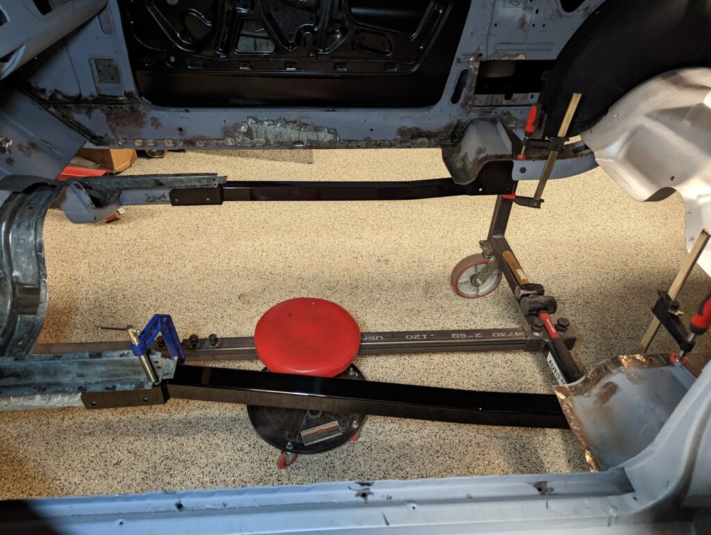
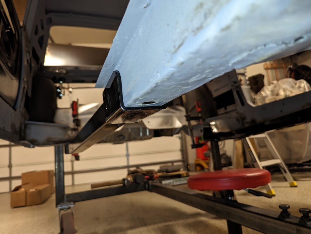
The front cups snugged up nicely against the front frame rails with a little bit of hammering and clamping.
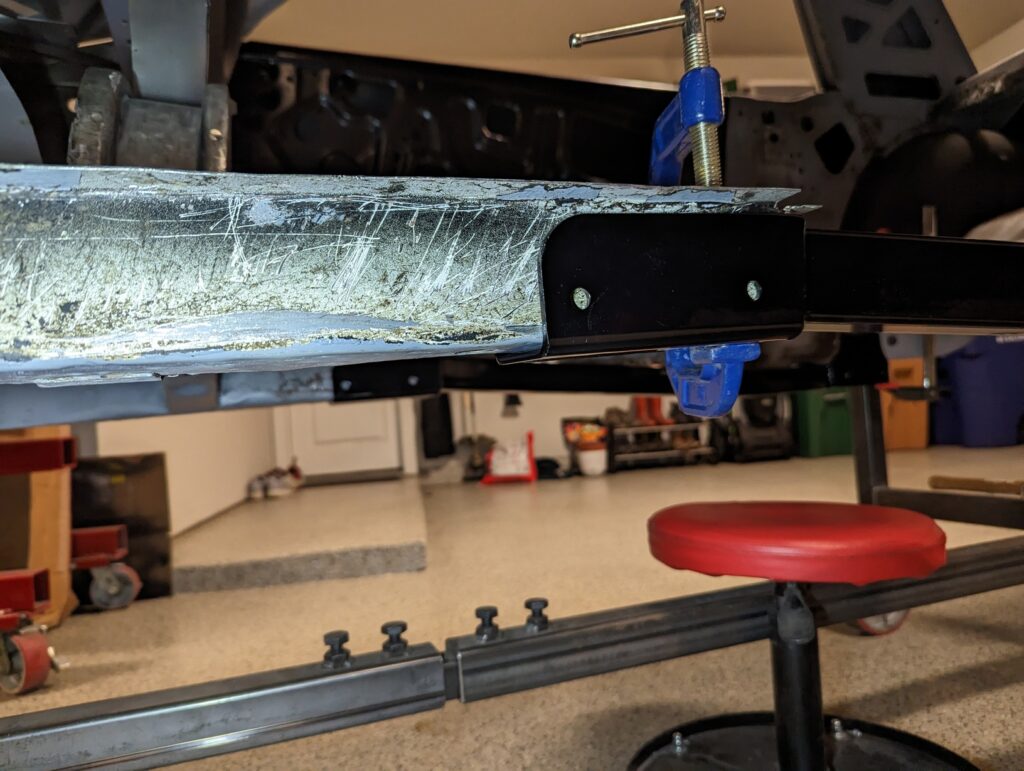
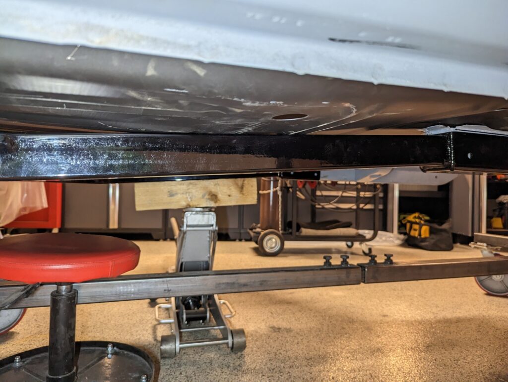
The fit on the rear of the subframe connectors was mostly good, but the furthest rear flange that’s intended to sit up against the torque box was maybe a quarter of an inch away on both sides of the car. The gap is visible on the left of the following picture.
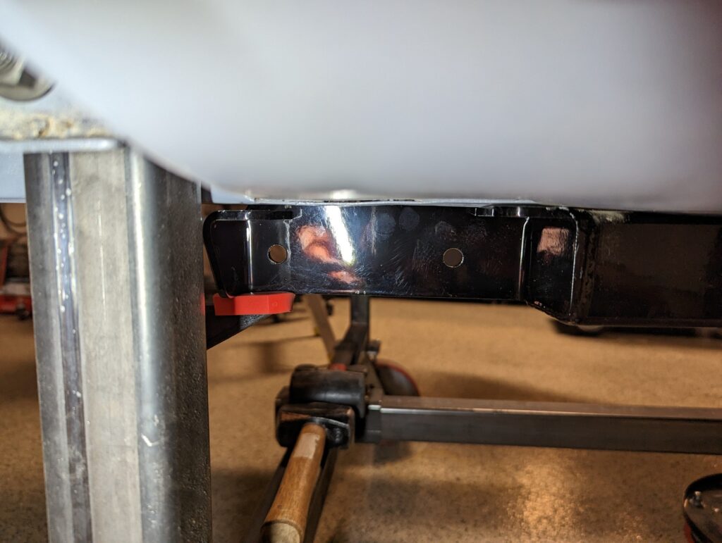
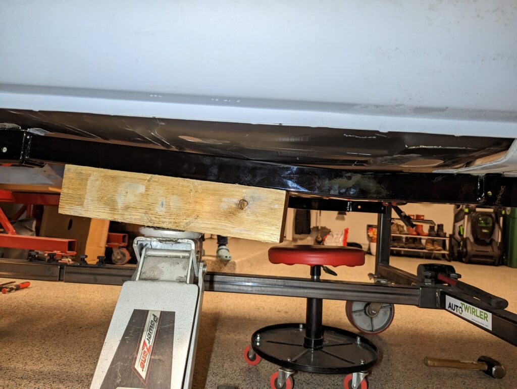
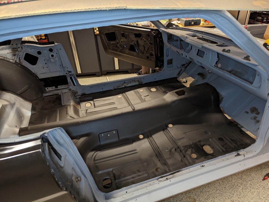
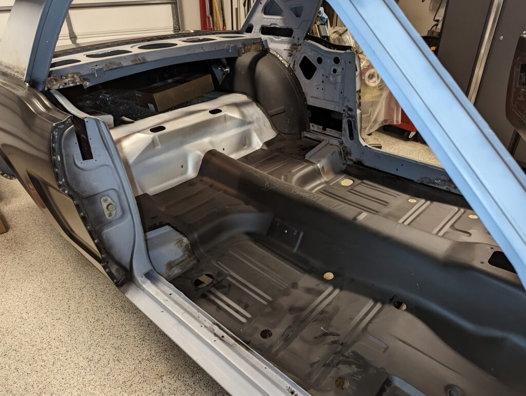
I wanted to take a look at the fit with the floor so I pulled the subframe connectors off, tossed the floor into the car and then used a floor jack to press the subframe connectors up into place.
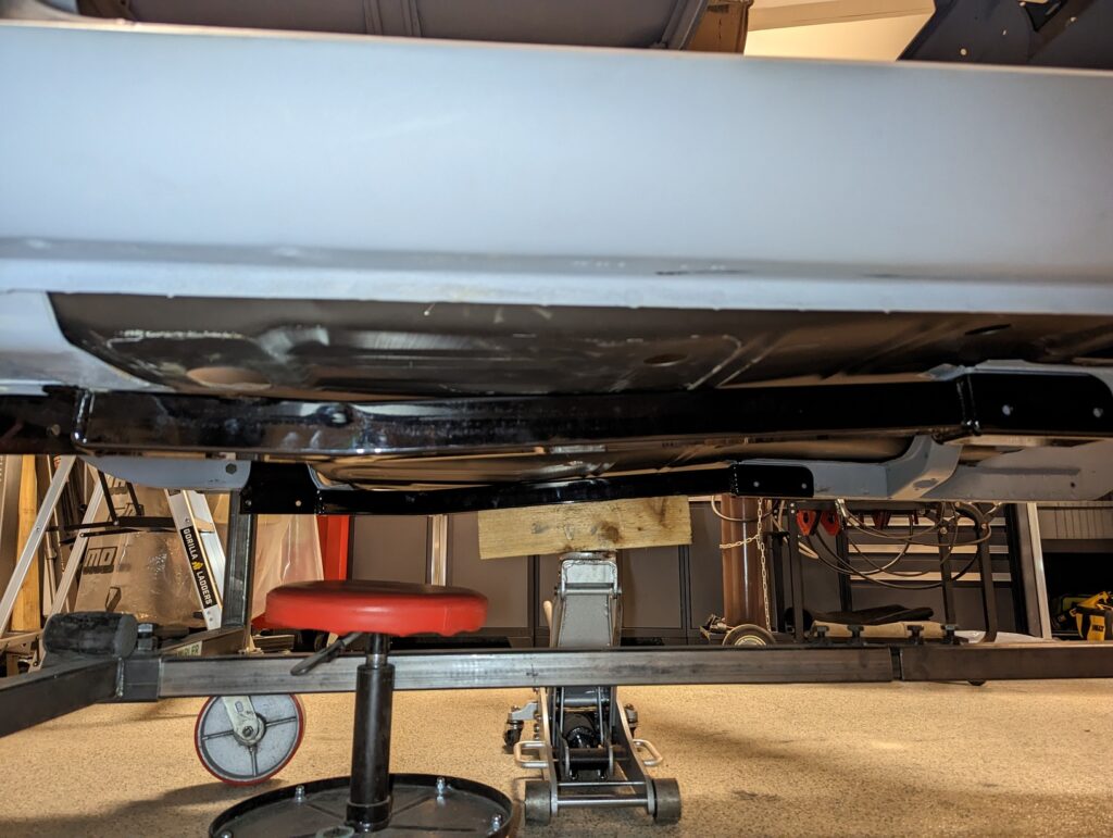
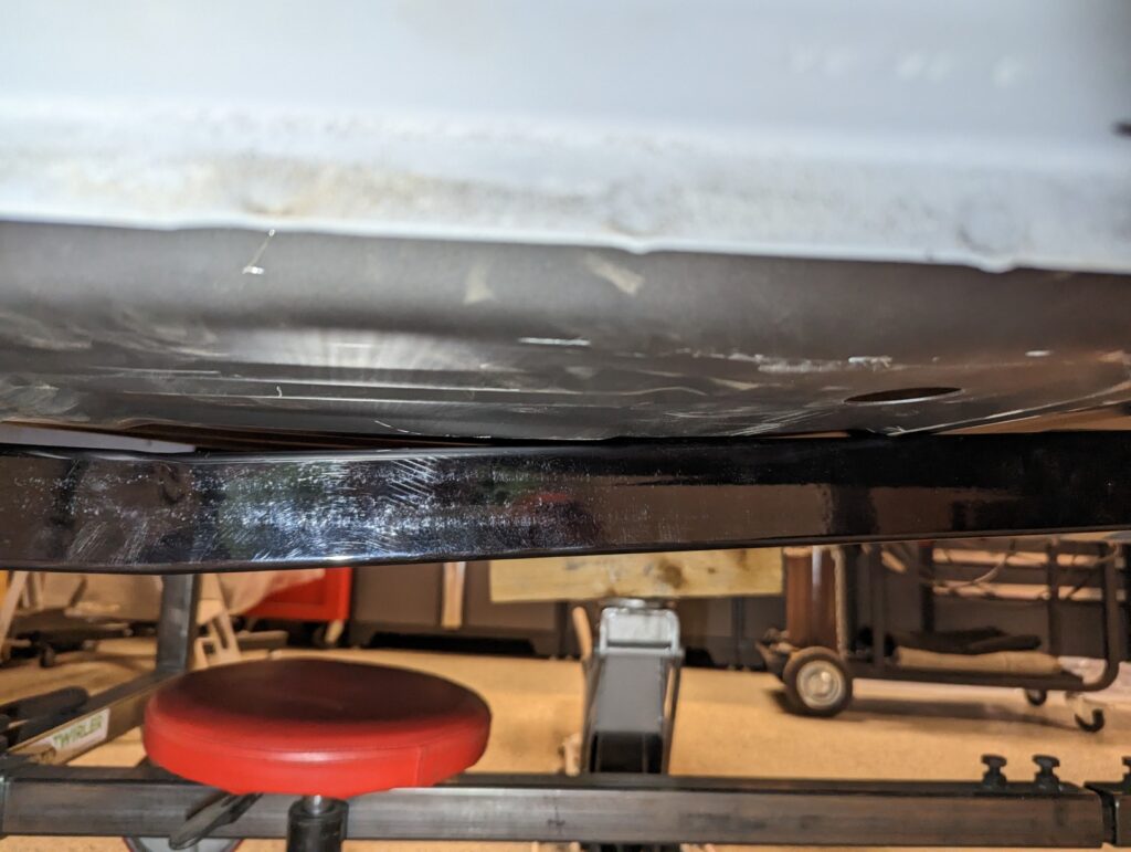
The floor wasn’t weighted down with anything, nor was the subframe connector pressed fully upwards in an effort to avoid any bending of the front frame rail. Even with those caveats it was clear where the initial interference between the floor and the subframe connectors would occur. I’m not too worried about it, I think the floor should be able to flex around it just fine. Didn’t see anything that convinced me that I need to start cutting up the floor to make room.
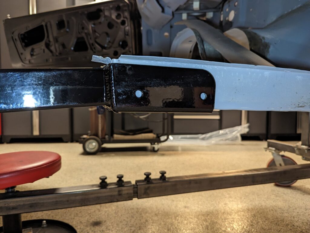
Good enough for a test fit!